Contact me! Email Gord (VA7GP)
In April 2011, I purchased a 5-band K4KIO HexBeam, from Leo Shoemaker - #302 he tells me. I bought the 5-band version, covering 20m, 17m, 15m, 12m and 10m.
I've built quite a number of antennae since I was first licensed in 1976. Interestingly, they've almost all been wire antennas, from a G5RV, single- and multi-band dipoles, and for 20 years - a 2-element Gem Quad. Time took it's toll on this Gem Quad: the UV degraded the fiberglass arms and the markets finished off the company :-(
I once had a Cushcraft R5 vertical in the late-1980's, but for the life of me, I have no recollection of what became of this antenna. I mention this only because it's a non-wire-antenna stand-out.
Enter the HexBeam: a little bit easier to assemble and handle than my Gem Quad, but still a directional, closed-loop(-ish) antenna (lower noise).
The HexBeam performed brilliantly ... sitting in my shed, unopened :-O
It took a further 9 years, until I was working-from-home for an extended period in Spring 2020 (due to COVID-19). With an extra hour (no chauffering to school, no commute) at both the start of the day and the end, I applied this extra time to tackle my HexBeam.
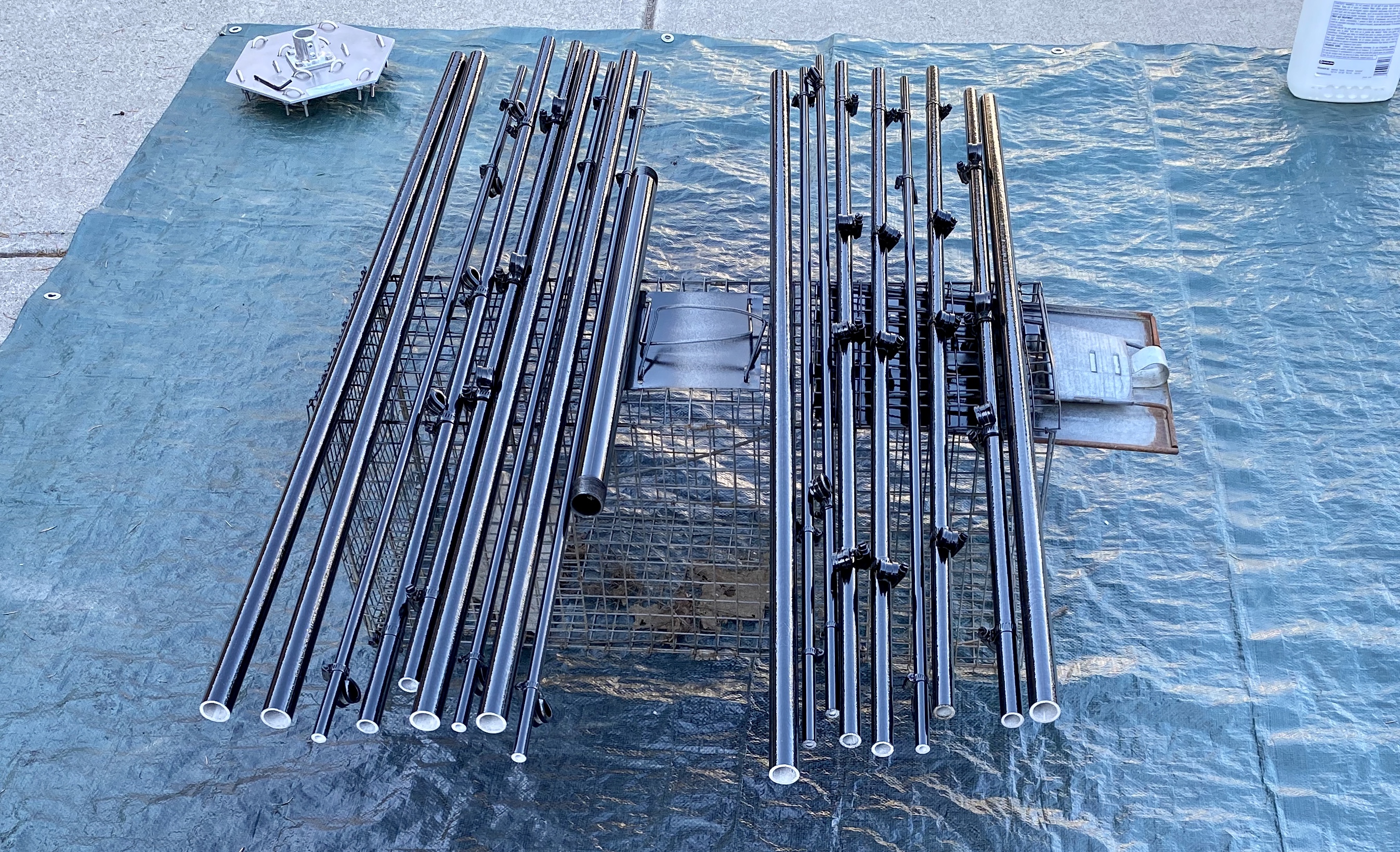
The last lesson from my Gem Quad gave me the starting-point for the HexBeam - paint! To slow UV-degradation. During this COVID-19 time, non-essential businesses were closed, and we were cautioned to leave our homes for essential reasons only. So - I had to scrounge and find a quart of left-over Tremclad paint in my shed, scrounge up acetone as both prep/cleaner and reducer, then spray:
Taking a cue from the latest Version 7 instructions on K4KIO's website, I unbolted the SpeedRail flanges, added Loctite Blue to the four bolts, and re-assembled the flanges back onto the Hexbeam plate.
I then installed the 1-1/4" black-iron pipe - it was a nice fit into the SpeedRail socket on the underside of the HexBeam plate. Loctite blue ought to prevent the set-screws from jiggling loose; a 1/4" bolt (Nyloc + Loctite!) pierced the joined assembly to prevent slippage/rotation, should the set-screws happen to loosen.

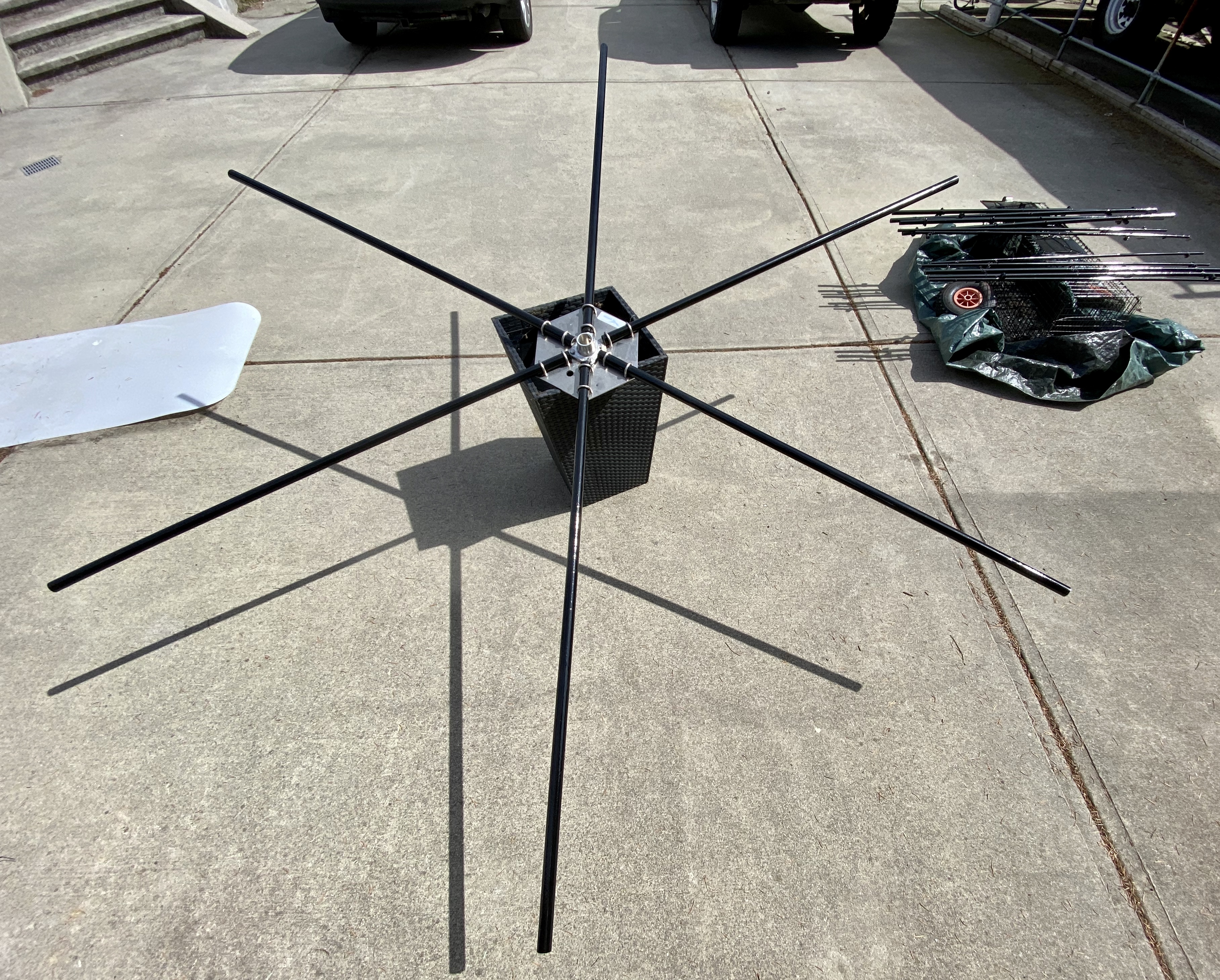
The spreader-arms will be in compression, so you may as well have the support of the flange for this force. Install the spreader-arms in opposing pairs; sight along each pair to line them up. Apply Loctite blue to the U-bolt threads (underside), then progressively snug each U-bolt nut. Look carefully, and if you see the very-slightest bit of flattening of the tube-curvature, STOP!

One of my wife's un-occupied planters was tall enough to accept the 24-inch mast, then provide support while assembling the spreader-arms to the base-plate. A garbage can would also have worked. Even without the mast-pipe, you'd want a convenient working-height.
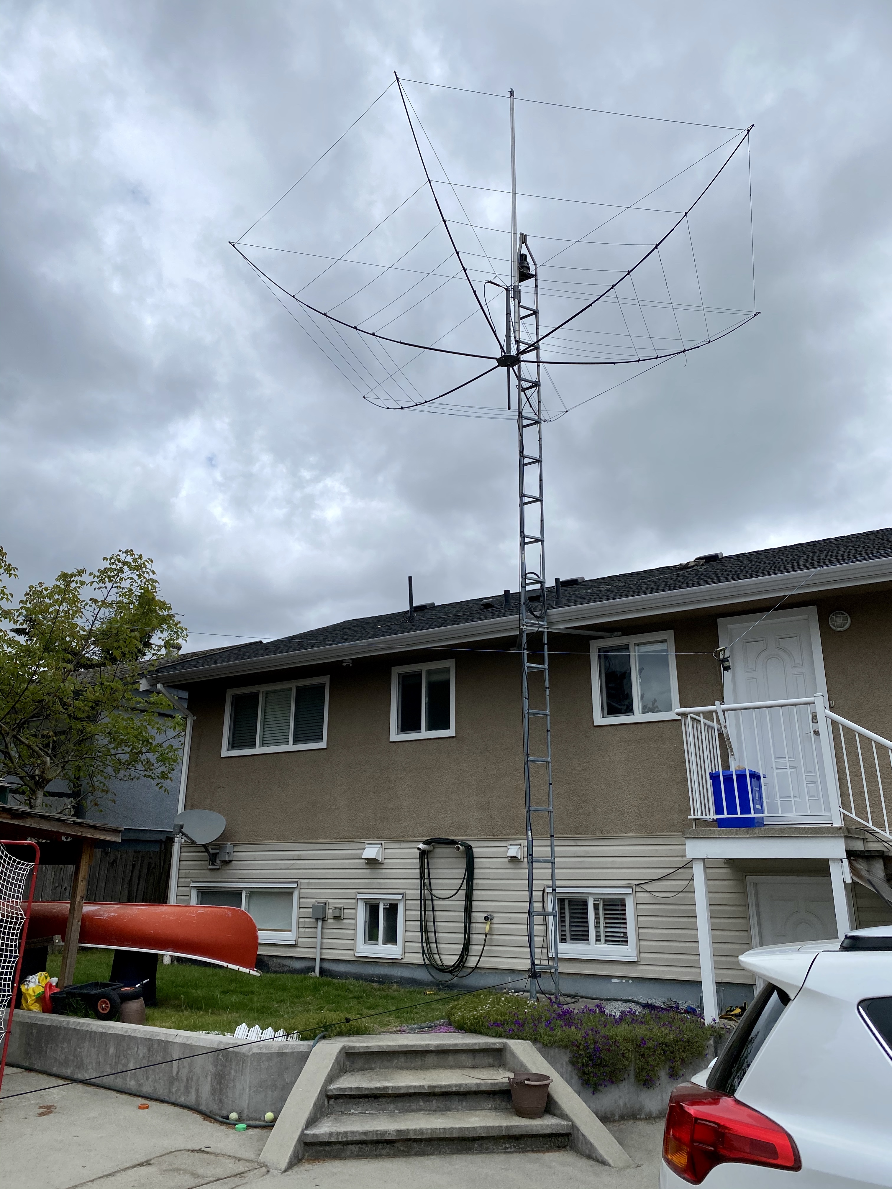
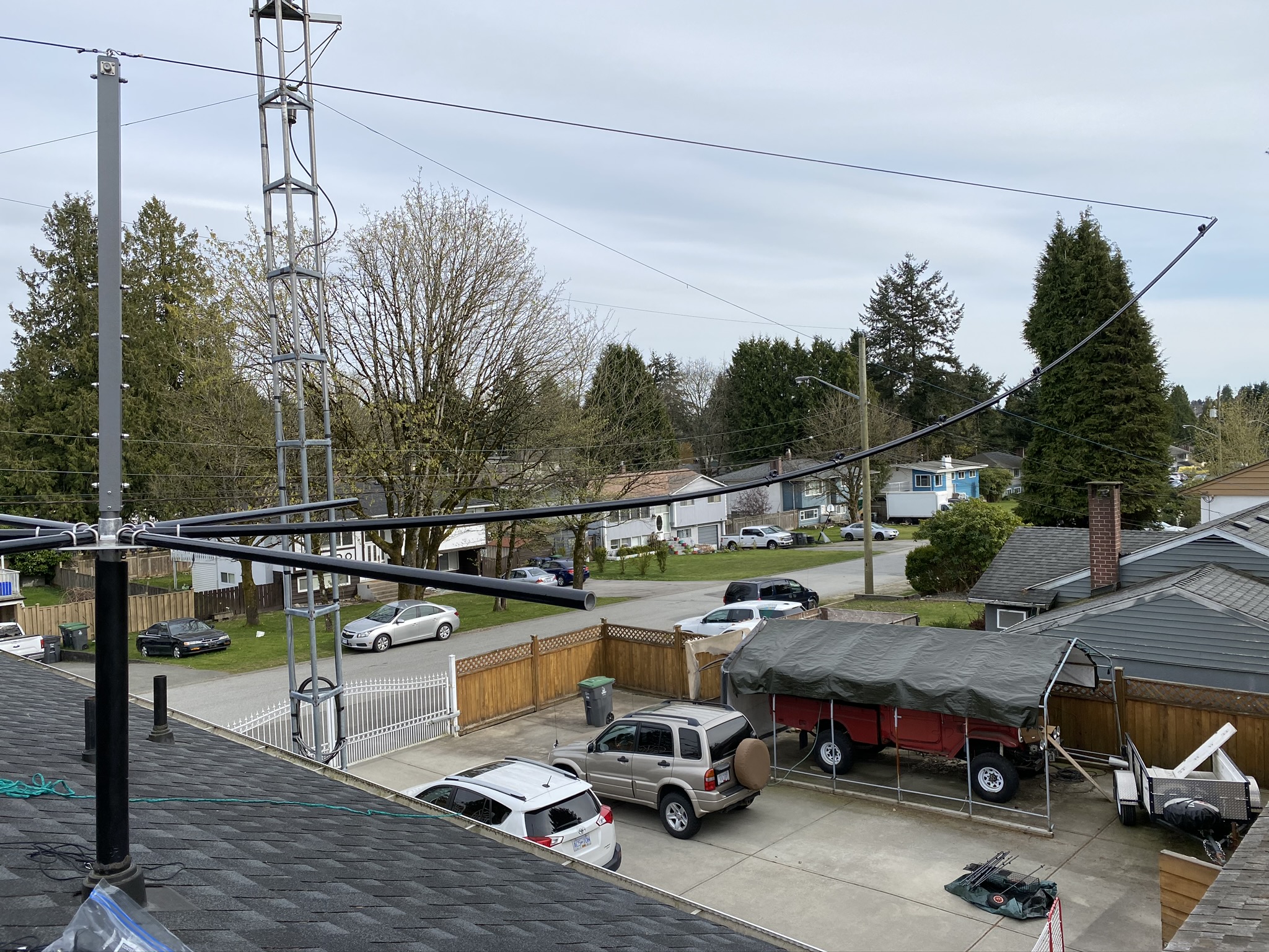
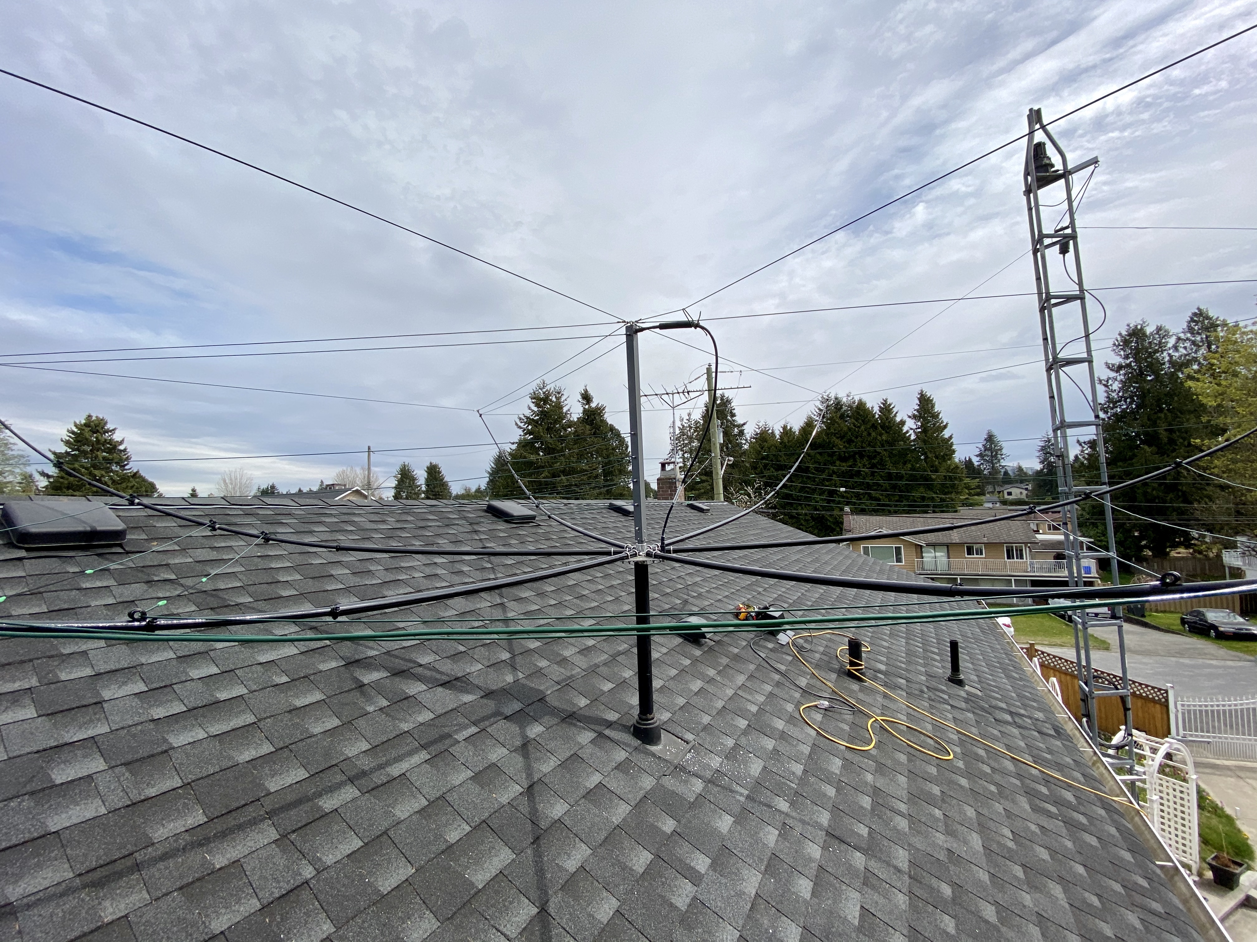
I decided to assemble the majority of my Hexbeam on the roof. However, I really had no idea how I was going to support and stabilize the antenna - I considered using a garbage-can, I considered removing the 2-foot pipe-mast. But fortune smiled on me :-) All my plumbing-vents could accept the 1-1/4 inch mast pipe, but one vent was high enough to actually work - by "work" I mean that the curvature of the spreader-arms and the pitch of my roof and the height of this one vent were absolutely *perfect* for the Hexbeam! And now, with the benefit of hindsight, I can see that simply slipping an ABS coupling, and an additional length of ABS vent-pipe could make any of my other (shorter) vents work just as well. BTW - lens-distortion makes my tower look like it's made of cooked-spaghetti :-O It's not - it's *dead-true* and it's solidly-affixed to my house-walls, with two under-eave braces, each attached to two tower-leg-tubes (anti-twist, very rigid).
then found plumbing-vents would accept the mast! Now is a good time to install the center-column, aligning the labels to determine "front". Loctite blue, and snug the set-screws. Slide an opposing-pair of middle- and end-sections of the spreader arms into the first set of tubes - P-clamps facing upward. Hook an opposing pair of support-cords into the ends (I used a third cord to extend the reach/pull of the first while I hooked the second one), then draw them upward and hook them both into the center-column eye-bolt - CAREFUL: don't apply lateral forces to the center-column!
Ground view of the first pair of spreader-arms and tension-cords:
Complete all six spreader arms and tension-cords (three opposing-pairs). How lucky I was, that the vent-pipe, roof-pitch, and Hexbeam spreader-curvature all worked beautifully!
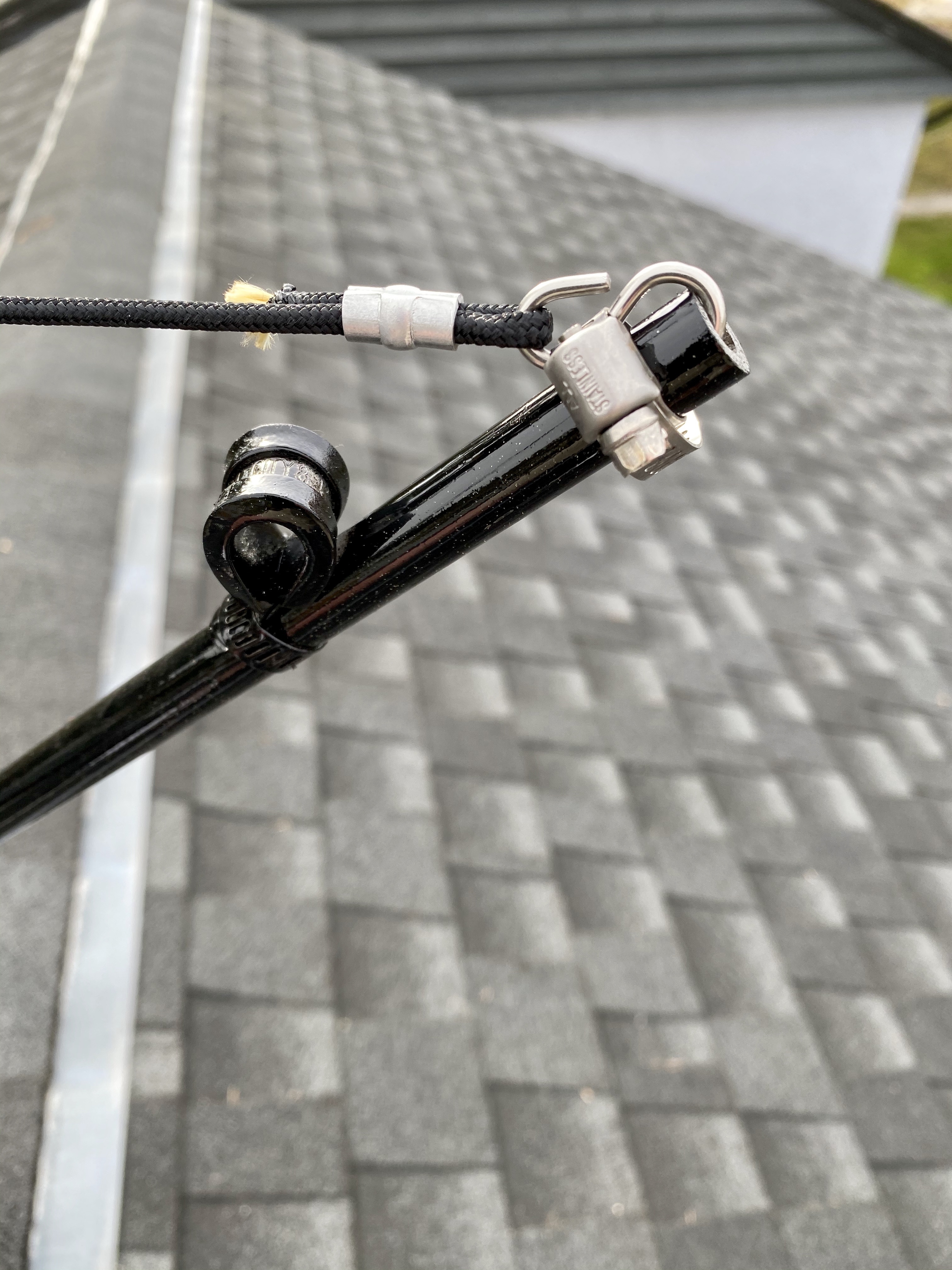
Detail showing support-cords hooked into spreader-arm. My original 2011 instructions (Version 5) say to secure the hooks with cable-ties, but Leo helpfully advised that these wouldn't last, and the updated parts and instructions now use hose-clamps. Again, during COVID-19 movement-restrictions, I couldn't just run to the hardware-store and buy these - Amazon came through, despite many non-essential items being delayed by a month to free-up delivery for urgent items.
Begin stringing the band-wires through the P-clamps, threading them around and around and around ... and around :-)
With an eye to longevity, I connected each element-wire by:
Assembly - Phase 2, On The Roof


Ideally, each metal-to-metal "micro-site" where conduction actually occurs would be entirely gas-tight. At 1.5kW power, expect about 5.5A. The wire-elements may look taught in these photos, but they are *NOT*! Shake and jiggle the antenna to get a feel for how much movement there can be, and definitely don't string them like a guitar :-O
Leo advised I *NOT* use the base-plate feed-through hole to pass my coaxial cable through - it would chafe (and the sharp edges of this hole guaranteed damage!). I also want to be able to remove the Hexbeam for rotator-service, antenna-service, etc. For this future maintainability, it's nice to have the cable easily detachable, but the top of the center-column is too far up to reach and undo :-(
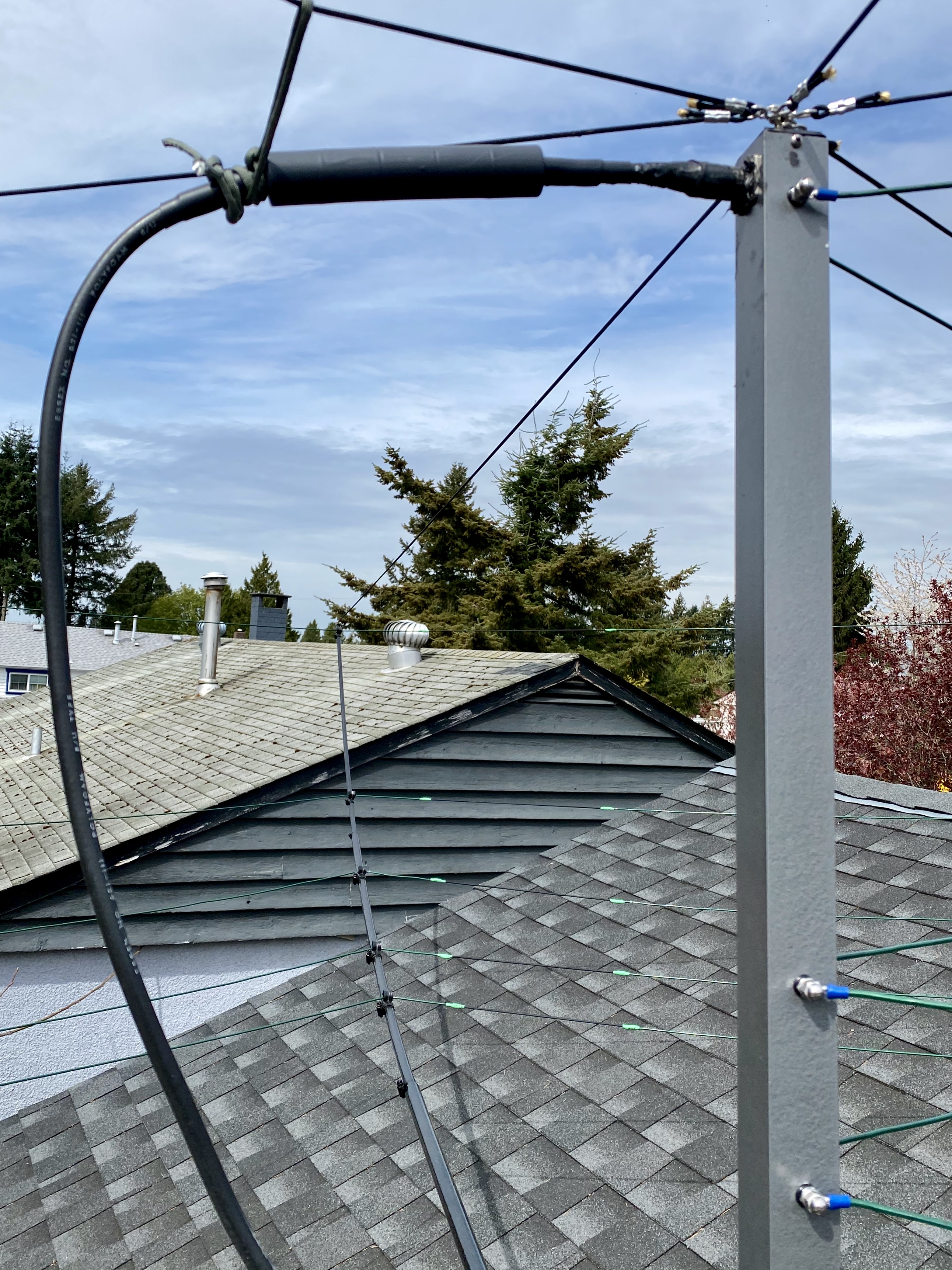
So - I decided to drill a 5/8-inch hole, install a 2-inch-long SO-239 barrel-connector into the base-plate, then make up a shorter feed-cable from the base to the SO-239 on the top/back of the center-column. In the future, from atop the tower, I can disconnect the feedline from the underside of the base-plate, then remove the antenna as needed.
It rains constantly for six-months in the Lower Mainland area of B.C., and I worried that moisture may migrate down the threads and into my co-ax... to address this, the barrel-connector has a generous filling of RTV sealant in the base-plate hole, and between the two mounting-nuts. The connector itself receives a blob of silicone-dielectric grease on the face of the SO-239 socket before connecting, and the PL-259 has a generous coating of RTV and double-layer of electrical-tape (pay attention to direction - overlapping layers must "shed" - the final wrap must start at the bottom and work upwards). Lastly, heatshrink over it all for neatness.
Oh sure, you ~COULD~ use COAX-SEAL, but that would be faster and far less messy :-)

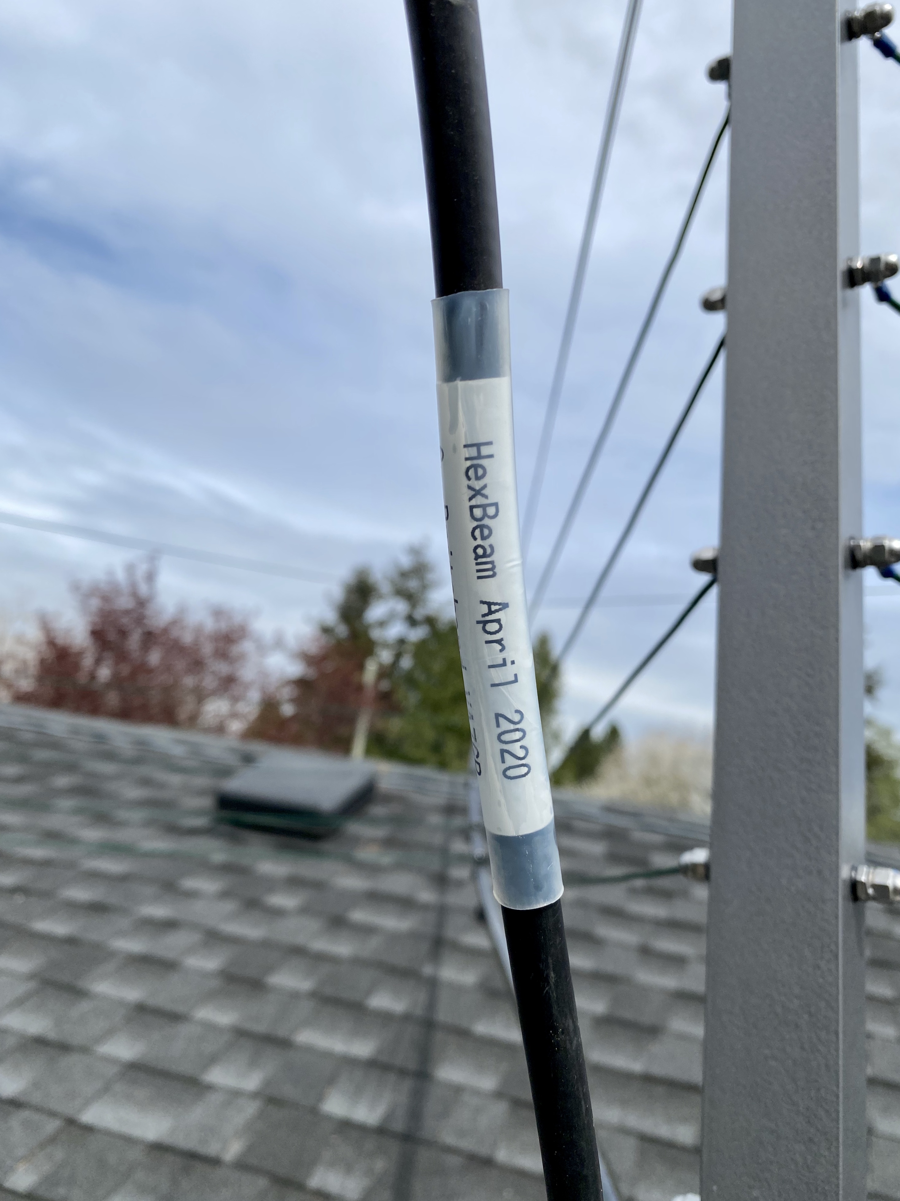
Signing the feedline:
I searched, and found that choking shield-current was necessary to provide good, symmetrical beam-pattern from this Hexbeam. Further, the location of the choke-balun is quite sensitive - below the base-plate allows the pattern to distort; it's recommended to apply choke at the feed-point. But that leads to another problem: how to support the choke weight? Attaching the feedline to the "hot" center-column didn't seem like a good idea...
Here is a photo of my Palomar Engineers BN-8 choke-balun, and the support-paracord I rigged up to cradle the weight of the BN-8 and relying on the supplied Dacron support-cords to hold it:
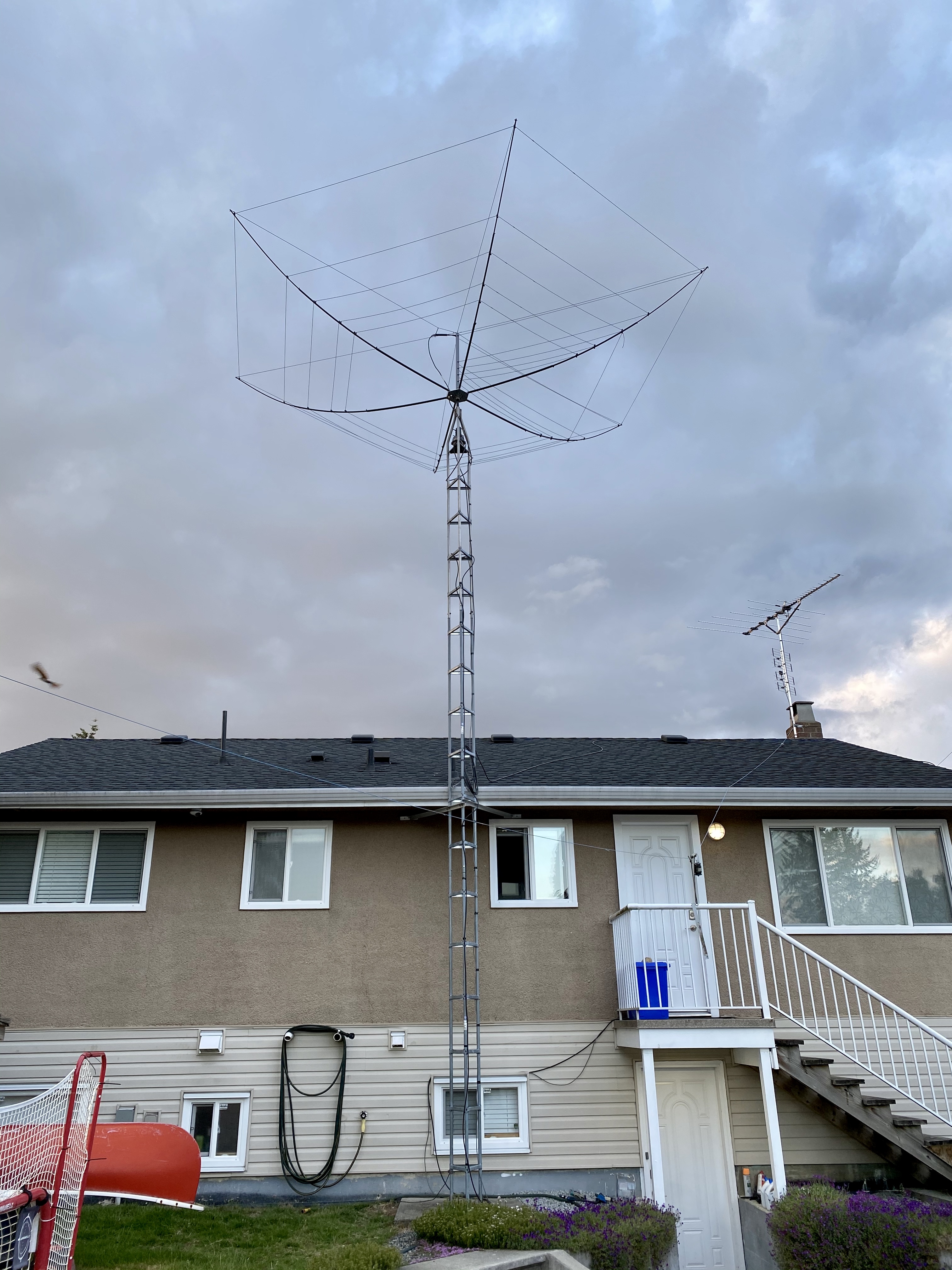
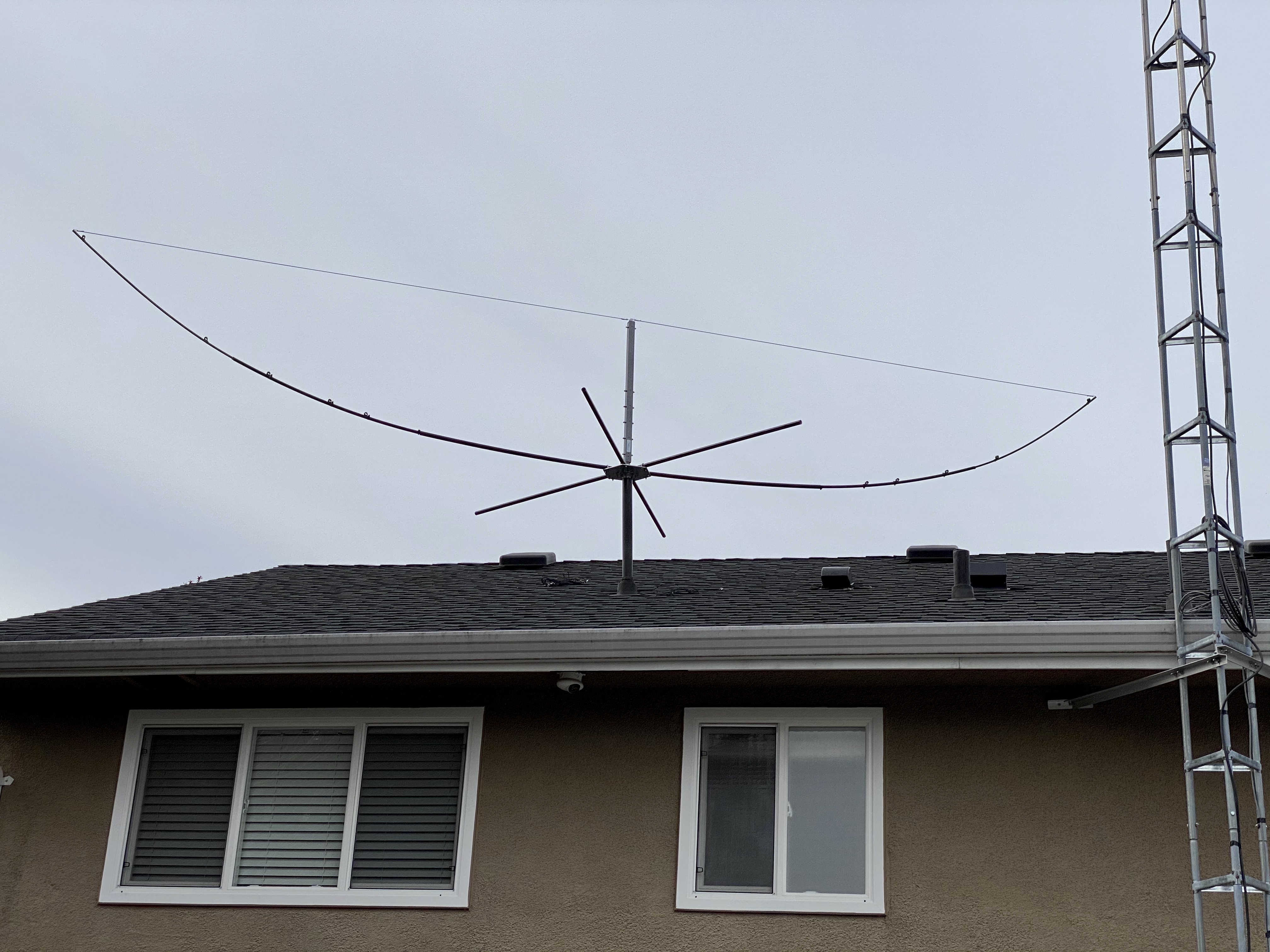
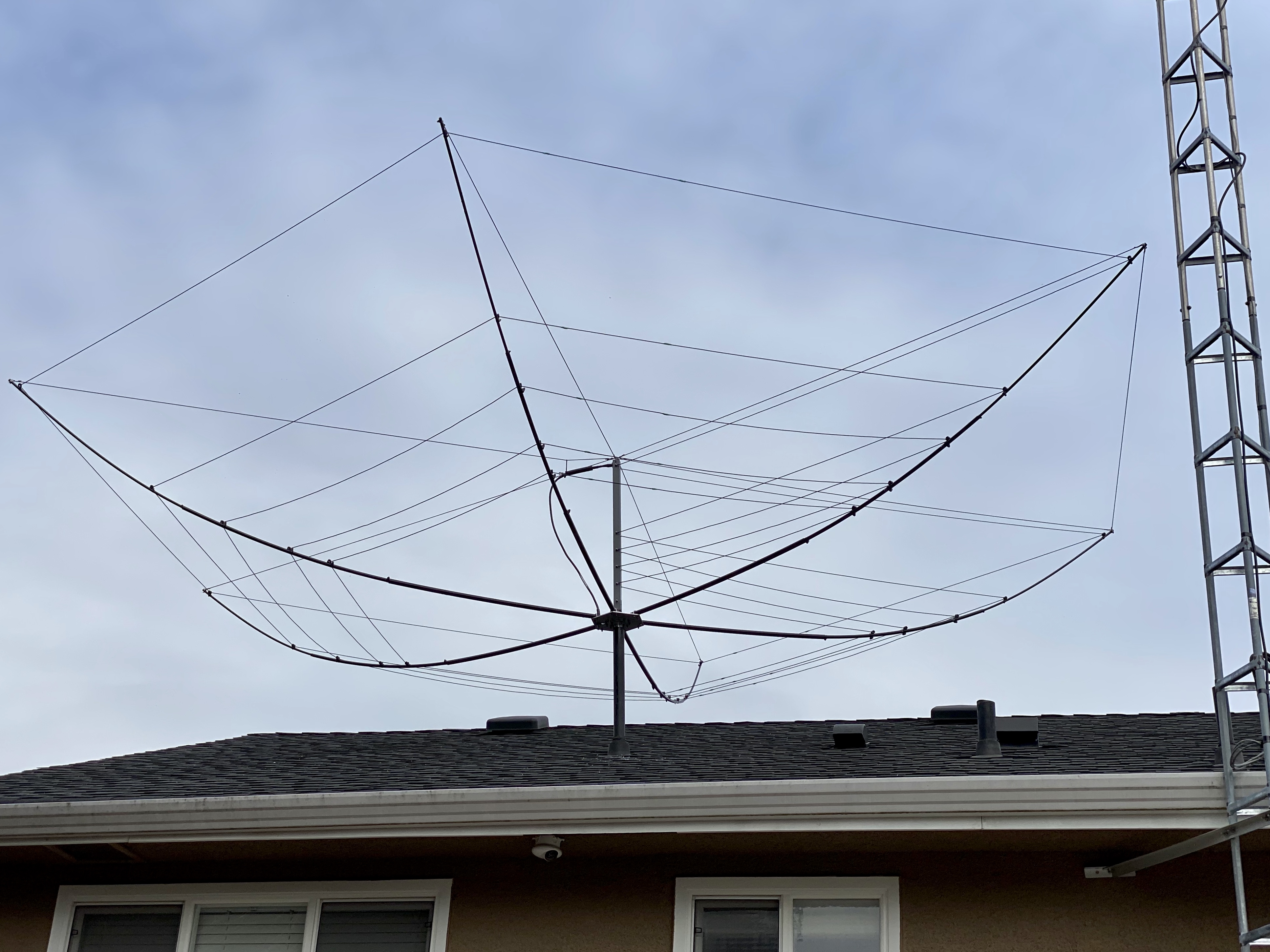
The completed Hexbeam assembly:
Ground view of the completed Hexbeam assembly:
Leo's DC (continuity, short) tests passed.
Connecting 75-feet of RG-8 allowed me to use my TS-850 transceiver and SWR-meter for further checking. I'm quite closely-coupled to my house-wiring, vents, ducts, etc. And to see truer antenna-performance, I really should sweep the SWR from the antenna-alone (not through co-ax)... One day, maybe, I'll get a VNA :-) But this test is enough to show that there are no faults in the Hexbeam; I'll cross my fingers that 20m improves when I re-position the Hexbeam atop my tower.

The basic assembly-completion plan: use the gin pole to take the weight of the HexBeam. The front-facing cords are not yet installed, so while it's hanging just above the roof, I'll move the "open mouth" right up to the tower, then spin it around 180-degrees - where I can stand on the roof and easily attach the final two cords.
Once the HexBeam is complete, I'll raise it above the top of the tower, then gently lower the mast-pipe down the tower-throat and into the rotator-throat. The tower-top is a simple 1-5/8 inch steel tube - I sleeved this with a Delrin bushing (1.5 inch o.d. and 1.125 inch i.d.). The Delrin bushing needed the side cut to allow expansion and fit over the mast. The fit is OK, and it will do the job (allow smooth rotation, without excessive lateral play) - my previous tower had a bearing, but this tower isn't designed with a bearing in-mind.