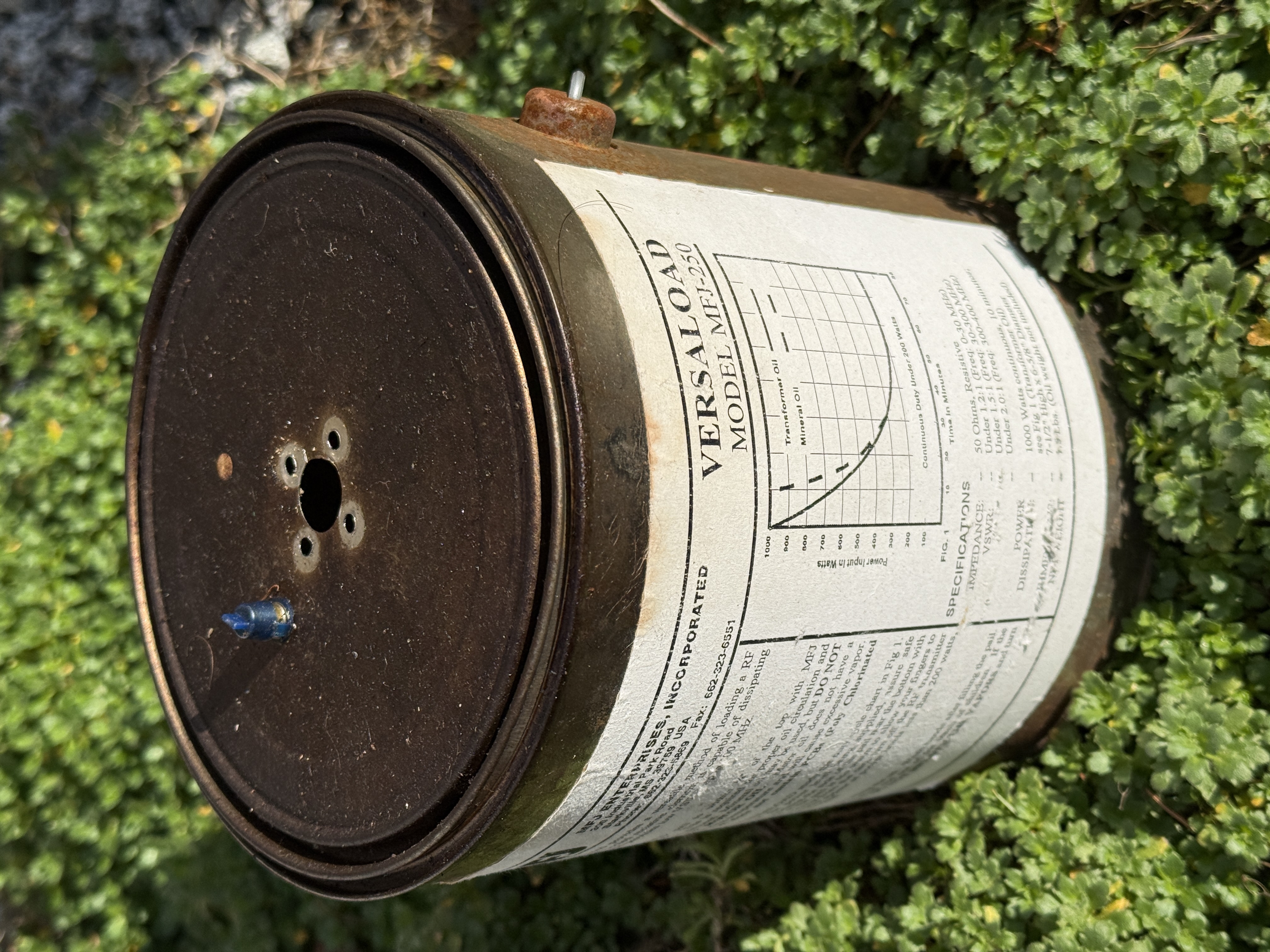

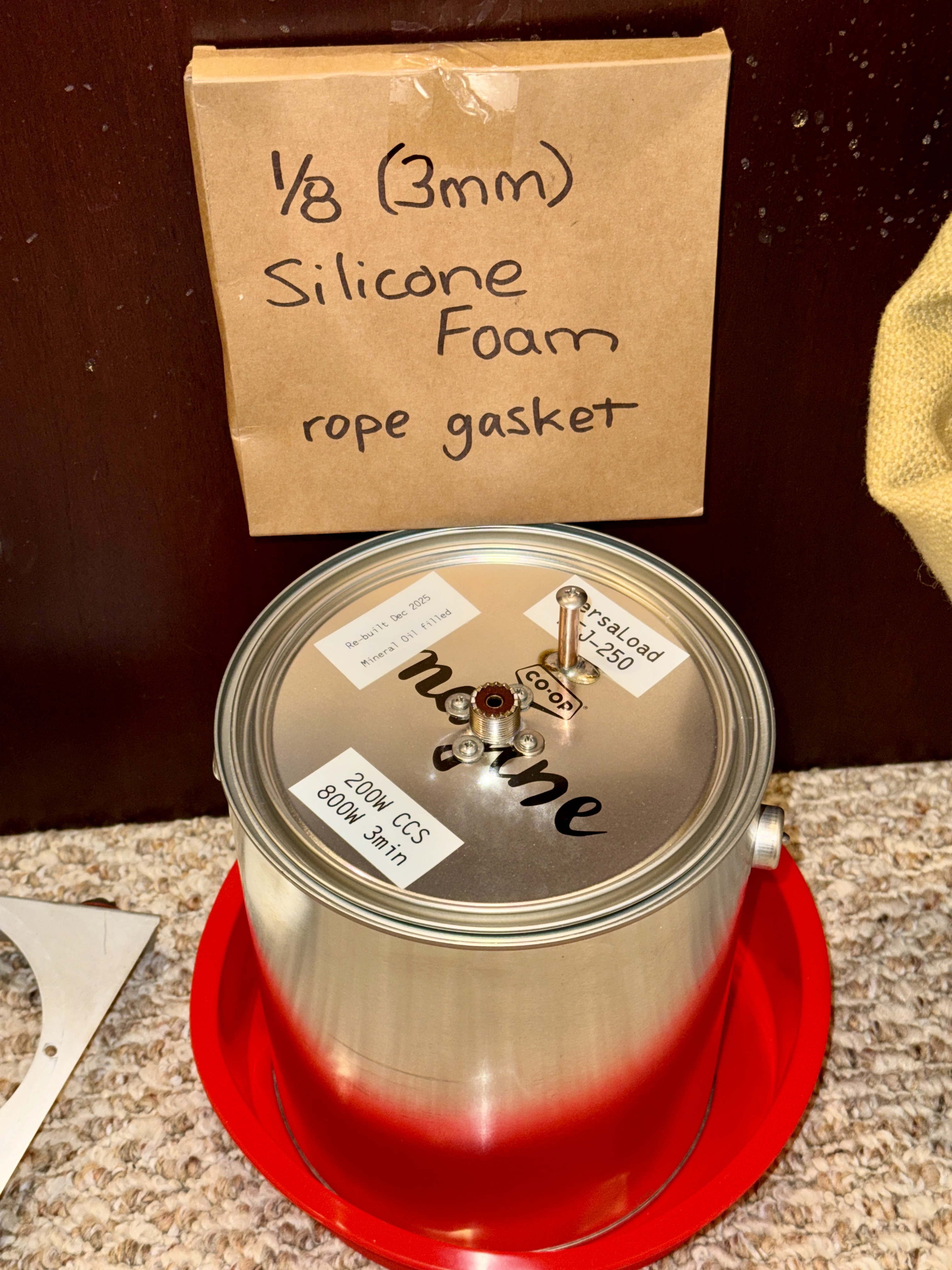
I went to my local Otter Co-Op farm-store, and bought a brand-new paint can, to re-home the guts of my MFJ-250. The paint-can is internally epoxy-coated. I made a taller vent-tube, by drilling the lid and soldering some copper-coated brake-line. A loose-fitting stainless sheet-metal screw drops into the tubing, allowing for thermal expansion of the oil and air-movement in and out.

|

|
I wanted to address the pervasive oil-leakage out of the original. The epoxy internal coating was the first step; soldering the vent-tube was the second step (MFJ originally used a short, stamped brass vent with plastic cap). The top mounting-surface of the original resistor-bracket received an alcohol-cleaning and thin coating of Permatex Grey RTV, intended to dissuade leakage up and around the SO-239 connector. The underside of the four washers also received a thin RTV coating. Lastly, I cut and fitted 3mm (1/8-inch) silicone foam rope into the top groove of the paint can. When the lid is installed, this rope gasket is somewhat compressed, in an effort to prevent oil-creep here too.
Amazon provided the 8-inch silicone cake-pan, as a final guard against oil leakage. And red is cool :-)
Otter Co-Op also provided the mineral-oil fill for this dummy load, at a reasonable price. Intended as a farm-animal laxative :-)

|
|
I found a few aspects of the MFJ-250 specifications that were "aspirational". Comparing the power-ratings of the Heath HN-31 and HN-31a to those on the MFJ Versaload, I decided to label mine as 200 Watts "Continuous Commercial Service". Good for exciters. And although I had applied 1kW previously to my MFJ, I felt better calling it 800W for 3min after considering all three loads' curves.
(Speaking of "aspirational", we can't forget Ameritron's ADL-1500! Claimed 1500W for 5min, but only using their transformer-oil! You can't get either the ADL-1500 nor their oil ... both now Unobtanium. Their notes warn that exceeding 30s may result in oil expulsion :-O Doubles as a science-fair volcano, I guess :-O )
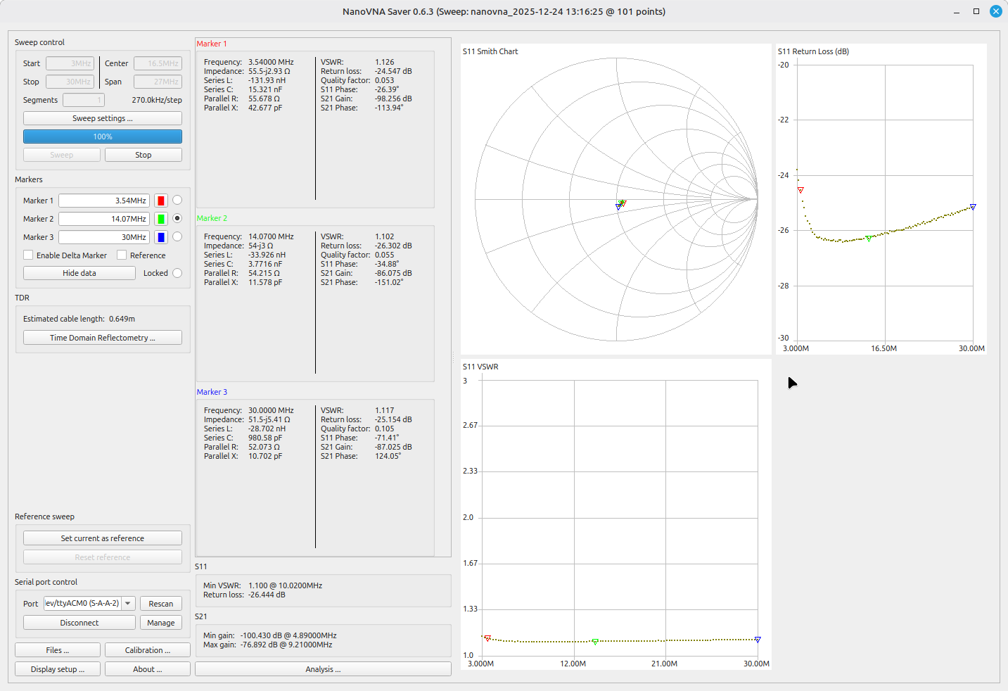
The DC resistance of my MFJ resistor: 55 ohms. This ought to provide about 1.10 VSWR, despite being at the outer fringe of tolerance. Perfectly serviceable.
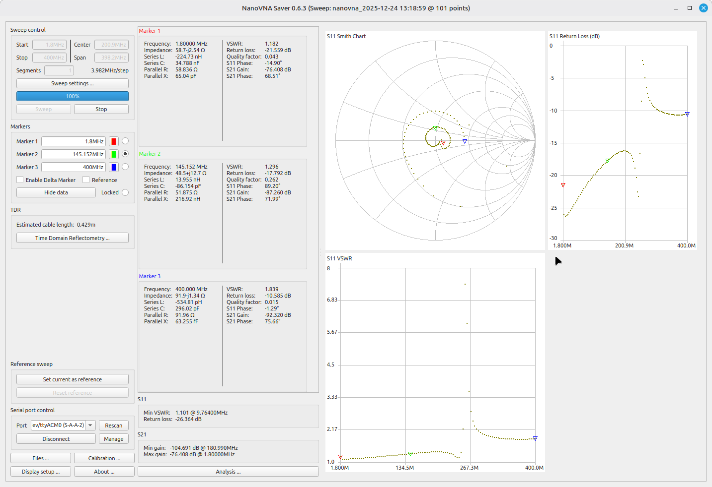
Using my nanoVNA, I also found the frequency / bandwidth spec's to be "aspirational" again. This shows clearly when comparing the Heath frequency range (to 2-metres/144MHz) with that of the MFJ (to 400MHz).
|
|
Summary: The MFJ-250 makes a great 3.5MHz - 30MHz dummy load, for the usual 100W ham transceiver.
NOTE: There are no longer any Amateur oil-filled dummy loads on the market, following the 2025 demise of MFJ. However, if you own one of these, it will serve for many decades so long as it's limitations are observed. Or, there are the 4-figure BirdRF Termaline products :-)
NOTE2: The Heathkit Cantenna (both HN-31 and HN-31a) had a cylindrical sleeve ("shield tube") surrounding the resistor. I have to wonder if this is better than my MFJ's three-sided square trough?? I've seen pictures of later models (esp. Ameritron ADL-1500) that added a fourth side to the square trough, and also featured some holes around the top to allow better oil convective-circulation. It would seem my MFJ-250 is among the earliest iterations, with the fewest "improvements". Very Special
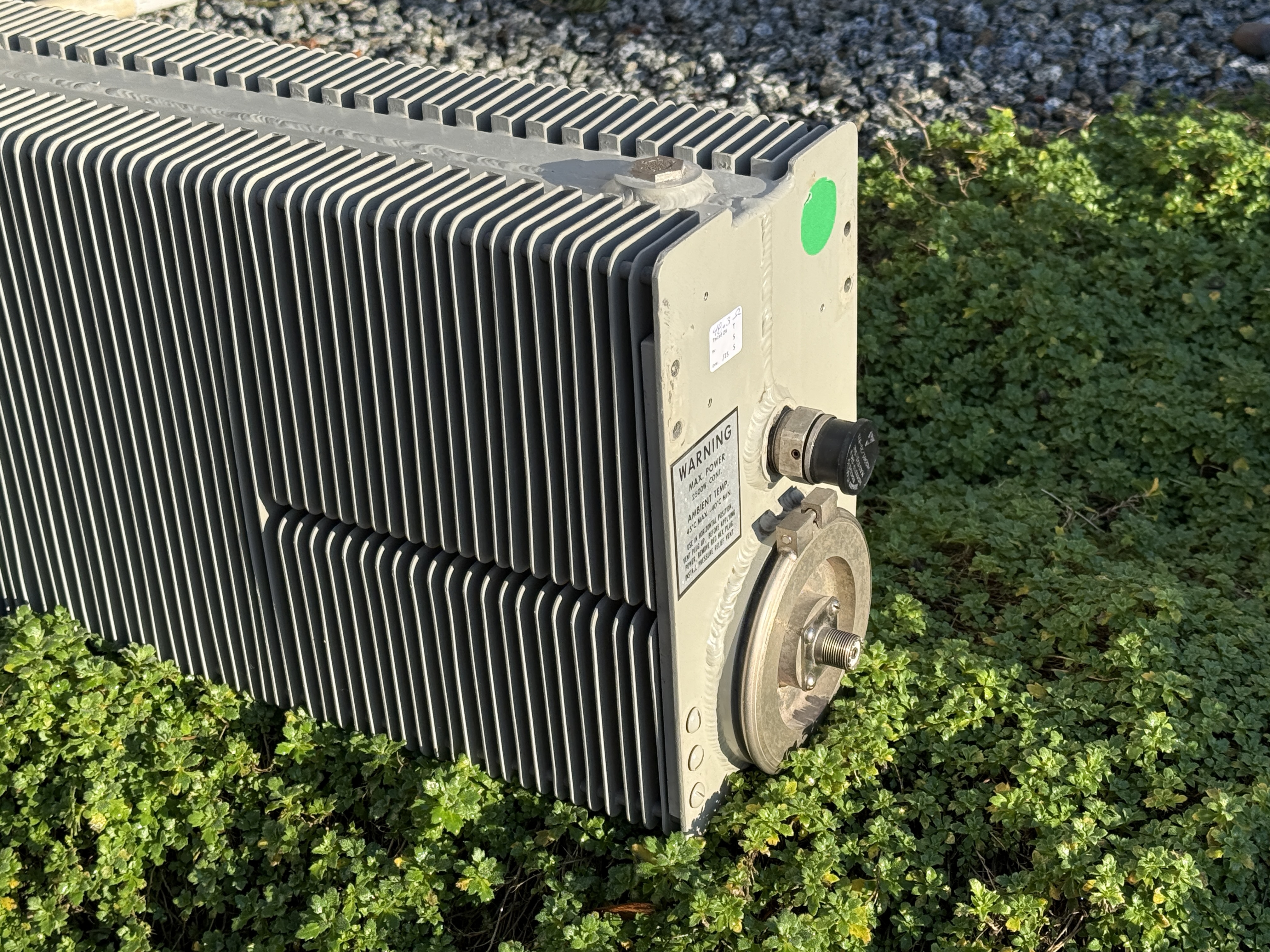

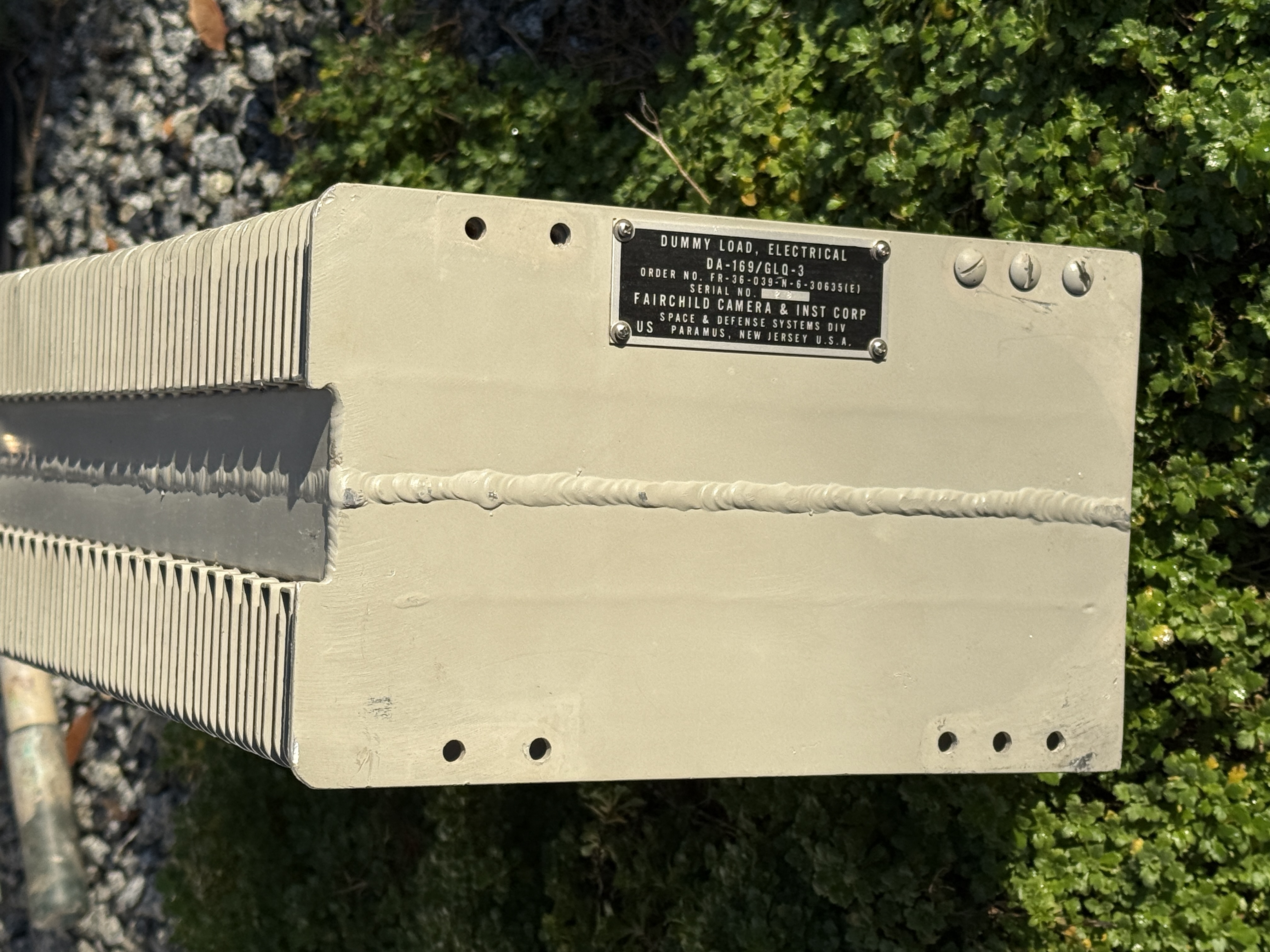
I filled it, per the Bird manual, to within 3 inches of the vent seat. So there is a couple of inches of air atop the oil. Roughly, my 8890 took 6 litres of Mineral Oil. I really, really doubt I'll ever heat the oil significantly, and I don't worry about oil-expansion expulsion.
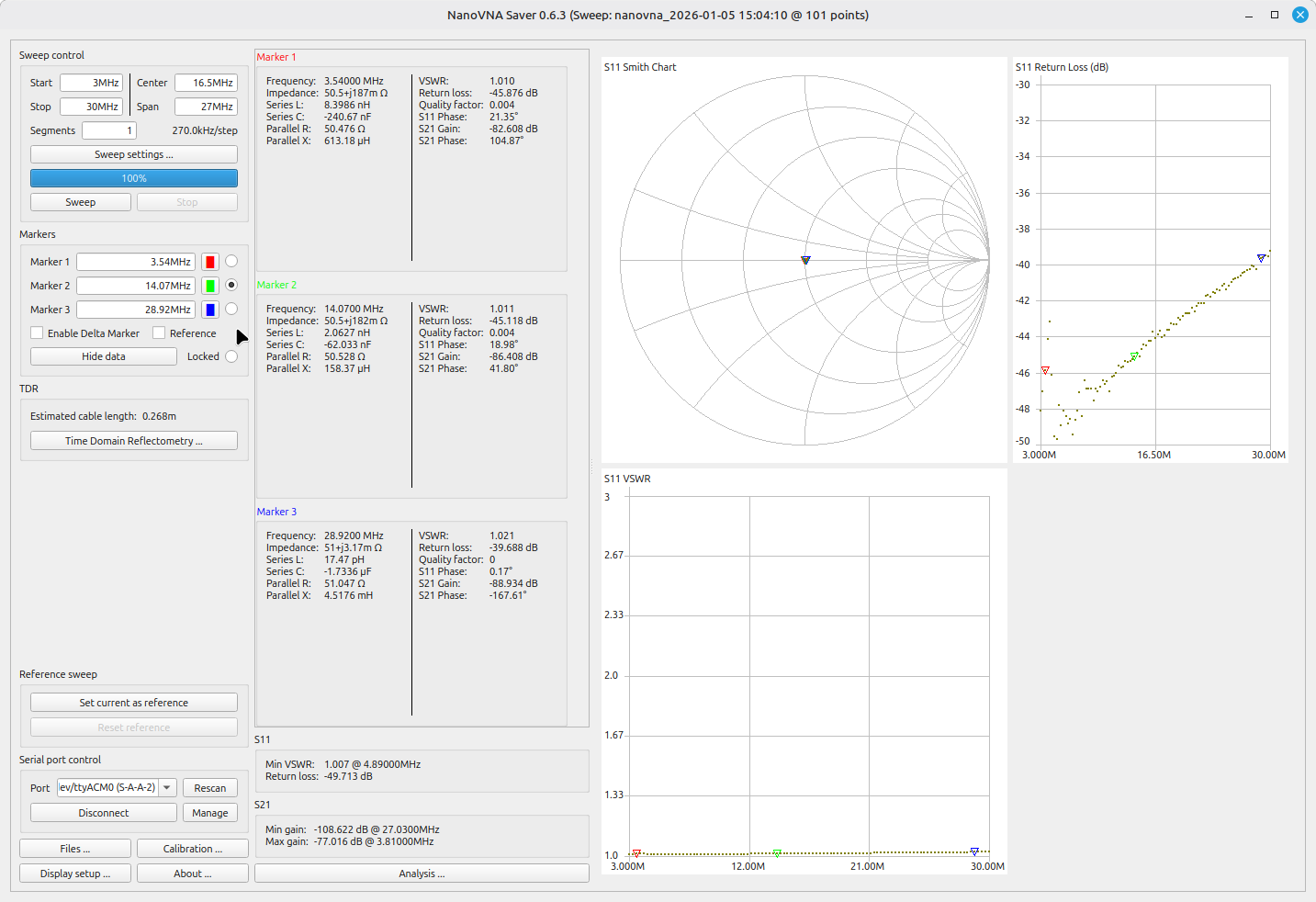
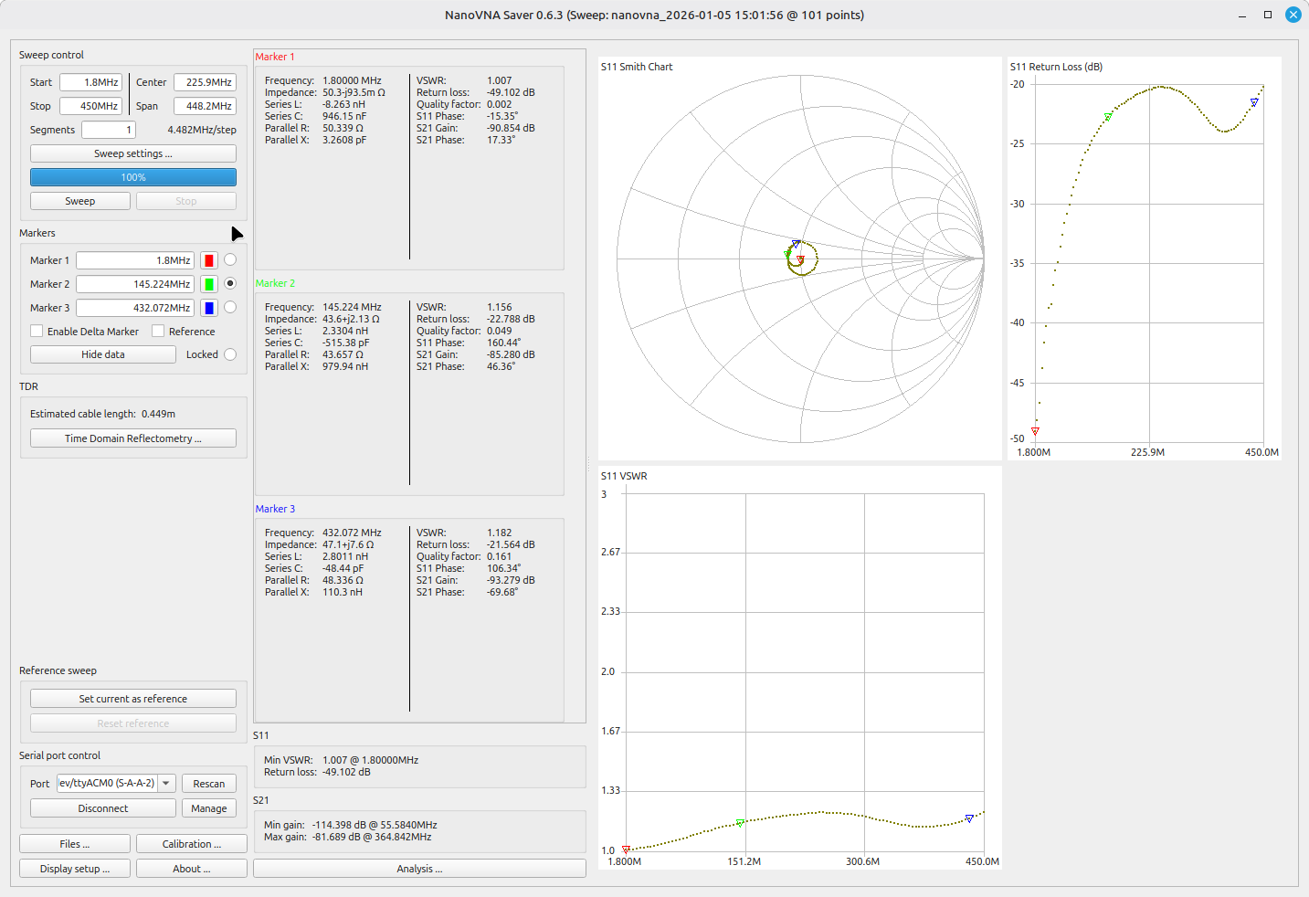
I emailed Bird, and this dummy load predated my correspondent's knowledge, and his ability to dig up any information. 50 ohms, 2500W CCS was all that was confirmed, so I dug out my nanoVNA and sorted out the usable frequency range ... draw your own conclusions, based on your own needs and circumstances:
|
|
And, just for fun, let's sweep right up to 2.4GHz (where many modern Bird 8890's are spec'd):
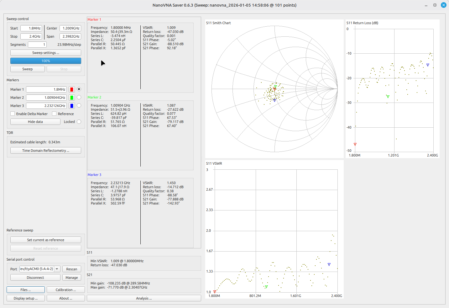
Summary: The Bird Termaline 8890 is an outstanding 3.5MHz - 30MHz dummy load, for the QRO ham amplifier. It can be used to higher frequencies, with careful evaluation of the required performance.
That's a very specific artifact. I can't find any public documentation of a Fairchild facility specifically in Paramus, NJ — their Space & Defense Systems Division was primarily at 300 Robbins Lane, Syosset, Long Island, NY, and their Clifton, NJ facility was the DuMont division (oscilloscopes, electron tubes). So the "Paramus" address on your unit is interesting — it may have been a sub-facility, a customer delivery address, or a smaller office that doesn't show up in the usual sources.
That said, given what the Space & Defense Systems Division was doing in the early 1960s, a 2500 W RF dummy load makes sense for testing high-power transmitters in the lab. The most likely programs:
Military/space communications transmitters — the division was building electronic systems for defense and space programs, and a 2500 W load is exactly what you'd need to bench-test a solid-state or tube transmitter at full rated output without radiating. Telemetry/data downlink transmitters for reconnaissance systems — Fairchild was deeply involved in the CORONA spy satellite film-recovery program and NASA's early earth-observation work. The downlink and tracking transmitters on those systems needed to be verified at full power. Air defense / SAGE-related communications — the early 1960s was the peak of the SAGE air defense network, heavily centered in the NY/NJ area. Fairchild's defense electronics work could have included high-power RF link equipment for those systems.
A serial number of 28 suggests it was one of a small batch — likely a dedicated lab instrument for a specific transmitter development program rather than general-purpose test gear.
If you can share a photo of the full label (especially any part numbers, frequency range, or contract numbers), I might be able to narrow down the specific program. Do you know the frequency band it was rated for?
Me:
I swept my 8890 dummy load with a vector network analyzer, and I would say it is an outstanding 50-ohm load throughout the HF region. Depending on the performance requirements, it would also be usable throughout the VHF and UHF frequencies if the required performance was acceptable (VSWR < 1.3 or return-loss > 20dB)
AI:
That's a great result, and it lines up well with the published specs for the modern 8890-300, which Bird rates at 1.1:1 max VSWR from DC to 1 GHz and 1.25:1 to 2 GHz. Your early unit hitting an "outstanding" 50 Ω match across HF and holding VSWR < 1.3 into VHF/UHF is essentially at or near the modern spec — impressive for a unit from ~1962.
Worth noting: Bird now makes a variant specifically for your use case — the 8890-300SC13 — which is optimized for 13.56 MHz semiconductor processing and claims VSWR < 1.05:1 from DC to 28 MHz. Your unit performing that well at HF means it's genuinely in that same class.
The tapered-resistor-in-oil design (which the older Model 81 manual describes as producing a "practically reflectionless line termination") is clearly what's giving it that flat response. The precision taper of the resistor housing is what makes the impedance transition smooth across frequency rather than resonant.
So to directly answer your original question — what Fairchild's Space & Defense Systems Division was doing that needed a 2500 W dummy load: given the contract number format and the era, the most likely application was bench-testing and aligning high-power transmitters for military/space communications. A 2500 W continuous-duty load that matches to 1.1:1 across HF is exactly what you'd need to develop and QA a transmitter that feeds into a satellite downlink, a ground-station link, or an air-defense communications system — all things Fairchild's defense division was deeply involved in during that period. The fact that it was built to such a high VSWR spec (rather than just "good enough") suggests it was used for precision alignment work, not just smoke-testing.